- Introduction
- ACI Basics
- Access Policies
- ACI VMM Integration
- Tenants
- Day 2 Operations
- Endpoint Security Group
- ACI Segmentation
- Nexus Dashboard
- Orchestrator
- Insights
- Conclusion
- References
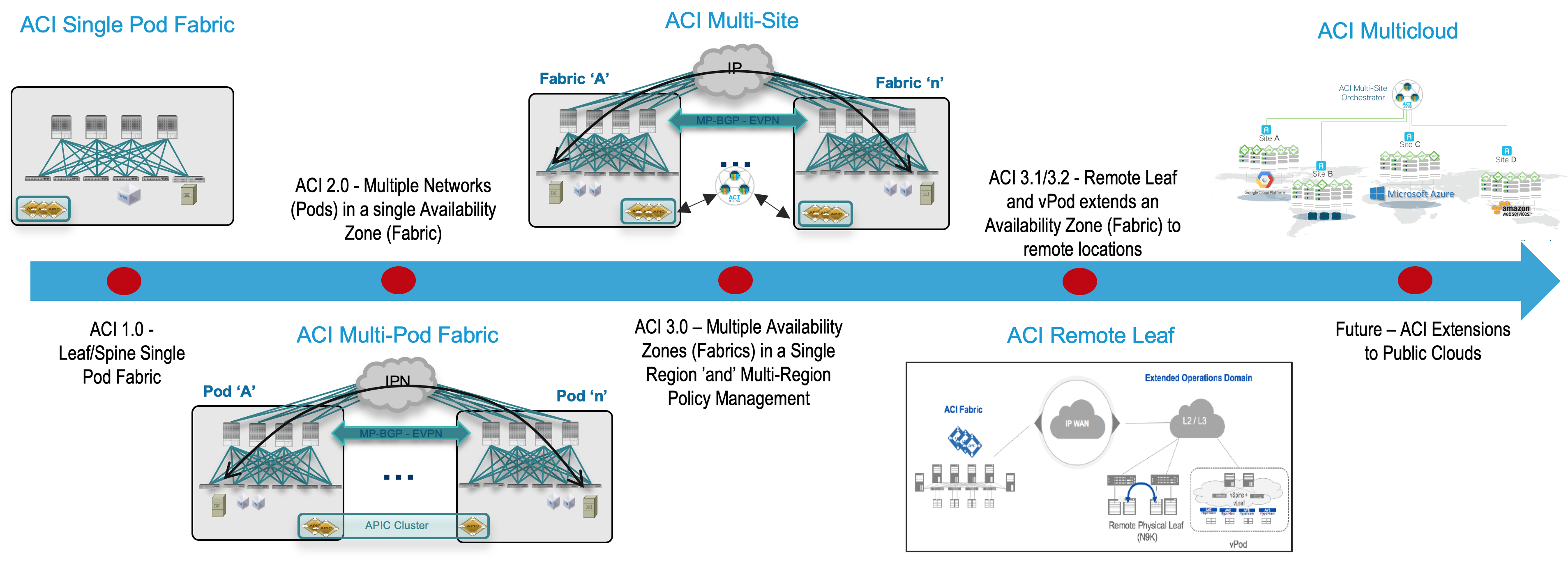
Before exploring the details of the Cisco ACI Multi-Site, you should understand why Cisco uses both Multi-Pod and Multi-Site architectures
and how you can position them to complement each other to meet different business requirements. To start, you should understand the main terminology used:
-
Pod: A pod is a leaf-and-spine network sharing a common control plane (Intermediate System–to–Intermediate System [ISIS], Border Gateway Protocol
[BGP],
Council of Oracle Protocol [COOP], etc.). A pod can be considered a single network fault domain.
-
Fabric: A fabric is the set of leaf and spine nodes under the control of the same APIC domain. Each fabric represents a separate tenant change
domain,
because every configuration and policy change applied in the APIC is applied across the fabric. A Cisco ACI fabric thus can be considered an
availability zone.
-
Multi-Pod: A Multi-Pod design consists of a single APIC domain with multiple leaf-and-spine networks (pods) interconnected. As a consequence, a
Multi-Pod
design is functionally a fabric (a single availability zone), but it does not represent a single network failure domain, because each pod runs a
separate
instance of control-plane protocols.
-
Multi-Site: A Multi-Site design is the architecture interconnecting multiple APIC cluster domains with their associated pods. A Multi-Site design
could
also be called a Multi-Fabric design, because it interconnects separate availability zones (fabrics), each deployed either as a single pod or
multiple
pods (a Multi-Pod design).

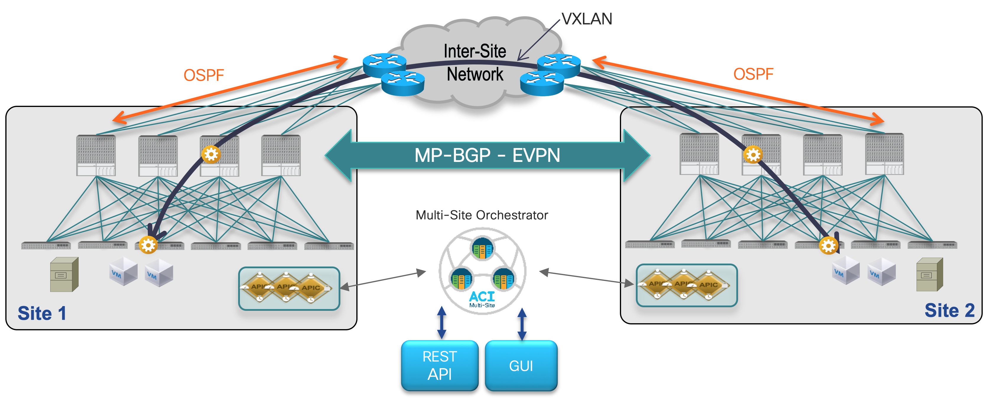
Multi-Site allows you to interconnect separate Cisco ACI APIC cluster domains (fabrics), each representing a different availability zone.
Doing so helps ensure multitenant Layer 2 and Layer 3 network connectivity across sites, and it also extends the policy domain end-to-end across the entire
system.
This design is achieved by using the following functional components:
-
Cisco ACI Multi-Site policy manager: This component is the intersite policy manager. It provides single-pane management accross sites, enabling you
to
monitor the health score state for all the interconnected sites. It also allows you to define, in a centralized place, all the intersite policies
that
can then be pushed to the different APIC domains for rendering them on the physical switches building those fabrics.
It thus provides a high degree of control over when and where to push those policies, hence allowing the tenant change domain separation that
uniquely
characterizes the Cisco ACI Multi-Site architecture.
-
Intersite control plane: Endpoint reachability information is exchanged across sites using a Multiprotocol-BGP (MP-BGP) Ethernet VPN (EVPN) control
plane.
This approach allows the exchange of MAC and IP address information for the endpoints that communicate across sites. MP-BGP EVPN sessions are
established
between the spine nodes deployed in separate fabrics.
-
Intersite data plane: All communication (Layer 2 or Layer 3) between endpoints connected to different sites is achieved by establishing site-to-site
Virtual Extensible LAN (VXLAN) tunnels across a generic IP network that interconnects the various sites. This IP network has no specific functional
requirements other than the capability to support routing and increased maximum transmission unit (MTU) size (given the overhead from the VXLAN
encapsulation).
The use of site-to-site VXLAN encapsulation greatly simplifies the configuration and functions required for the intersite IP network.
It also allows network and policy information (metadata) to be carried across sites.

The Inter-Site Network (ISN) requires only that the upstream router the ACI Spines connect supports OSPF and sub-interfaces. A sub-interface with
encapsulation VLAN 4
is used between the Spine interface(s) and the upstream ISN router interface(s). The only other requirement is for increased MTU support for the VXLAN
encapsulation overhead.


